SolidWorks Tutorial几何提取.docx
《SolidWorks Tutorial几何提取.docx》由会员分享,可在线阅读,更多相关《SolidWorks Tutorial几何提取.docx(12页珍藏版)》请在冰点文库上搜索。
SolidWorksTutorial几何提取
SolidWorksTutorial:
ExternalGearPump
AaronHeisler
UniversityofWisconsin
PowertrainControlResearchLaboratory
May23,2008
Goal:
ThepurposeofthisdocumentistoassistPumpLinxusersintransferringaCADfileofanexternalgearpumpmodeledinSolidWorkstotherequiredSTLfileformatforPumpLinx.
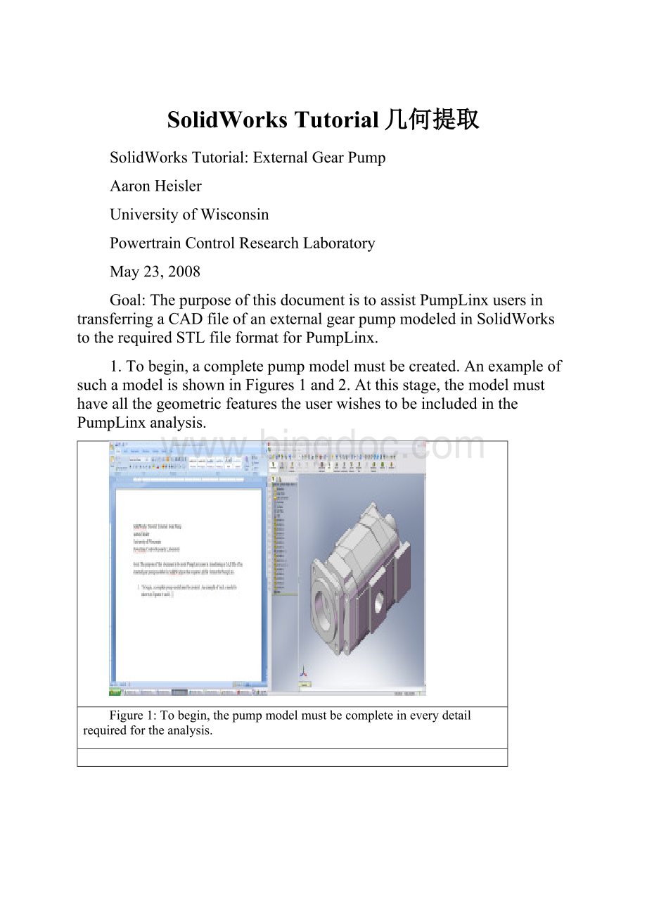
1.Tobegin,acompletepumpmodelmustbecreated.AnexampleofsuchamodelisshowninFigures1and2.Atthisstage,themodelmusthaveallthegeometricfeaturestheuserwishestobeincludedinthePumpLinxanalysis.
Figure1:
Tobegin,thepumpmodelmustbecompleteineverydetailrequiredfortheanalysis.
Figure2:
Thegeartimingisimportantatthisstageintheanalysis.
Thereareafewareaswhichneedspecialattentionsothesimulationcanbeproperlyset-up.Theseissuesincludethefollowing:
∙Thesidefaceofthegearmusthavezerogapbetweenitandthebushing.
∙Thegapsbetweentheteethmustbelargeenoughthatthegearsdonotcrossatanypointduringarevolutionoftheinputshaft.ForthepumpshowninFigures1and2,theminimumgapwasapproximately0.0034in.Themagnitudeofthegapwilldependupontheindividualpumpdesign.
∙Theexactcenterlocationofthegearsmustbeknown.Forsimplificationlateron,matetheassemblyorigintothecenterofoneofthebottomgearsandaddparallelmatesbetweentheassemblyplanesandpartplanes.Thepurposeofthisstepistoensurethatthepumpisalignedtoaspecificcoordinatesystemthatcanbeeasilyreferencedatanypointintime.
2.Nowthatthepumpgeometryisfinishedtothelevelofdetaildesiredfortheanalysis,thefluidregionmustbeextracted.Thisisdoneintwodistinctsteps.Thefirststepextractsthefluidencompassedbytheapproximate“figure8”volumethegearspassthroughduringonerevolutionoftheinputshaft.Toextractthisvolume,executethefollowingsteps:
a.Openanewpart.
b.Drawacircleinanyreferenceplane.Dimensionthecirclesoitexactlymatchesthediameterofthehousingwherethegearislocated(seeFigure3).
c.Drawacircleofequaldiametertocreatea“figure8”shapedsketchthatfillsthevoidinsidethehousingshowninFigure3.ThefinalsketchshouldlooksimilartothatshowninFigure4.
Figure3:
Thenewpartmusthavethesamediameterastheholesboredinthehousingenclosingthegears.
Figure4:
The“figure8”shapedpartbeginsasadrawingcontainingtwoequaldiametercircleswithaknowncenterdistance.
d.Extrudethisshapetotheexactwidthofthegears.ThefinalpartshouldbesimilartothevolumeshowninFigure5.
Figure5:
Extrudethesketchtotheexactwidthofthegears.
e.Thispartistheninsertedintothepumpassemblyandmatedsuchthatitfillstheaforementionedvoidencasingthegears.Thegearoutlinewillstillbevisiblesincebothpartsaretheexactsamethickness.
Figure6:
Thenewpartisinsertedintotheassemblyandmatedsuchthatitencapsulatesthepairofgearsandfillsthehousingbore.
f.Selectthenewpart,andclick“EditComponent”inthemaintoolbar.Thengoto“Insert”–“Mold”–“Cavity”asshowninFigure7.For“DesignComponents”selectthetwogearsthatthispartencapsulatesfromthetreethenclickOK.Keep“ComponentOrigins”,“UniformScaling”,and“0.00%”fortheoptions.
Figure7:
Toextractthefluidregionaroundthegears,the“Cavity”featurewillbeused.Specialcaremustbetakentoensuretheproperregionisextracted.
Figure8:
Selectthetwogearswhichthepartisinplanewithunder“DesignComponents”andensurenoscalingisapplied.
g.Anewwindowwillopentitled“BodiestoKeep”.Clickthe“Selectedbodies”buttonandselectthebodythatisthenewpartminusthegearvolume.ThesmallvolumesatthecenterofthegearsinFigure9shouldnotbesavedasthoseregionsdonotcontainfluidintheactualpump.
Figure9:
Multiplevolumesarecreatedwhenthe“Cavity”functionisused.Picktheappropriatebodywhichequatestothevolumeoffluidtrappedaroundthegears.
h.Thispartisnowfinished.Repeatthisprocessforeachpairofgearspresentinthepump.
Figure10:
Thefinishedpartistheoriginal“figure8”shapewiththegearvolumesubtracted.Thisisthefirstofthetwofluidregionsrequiredandneedstobedoneforeachpairofgears.
3.Thesecondfluidvolumecannowbeextractedfromthegearpumpassembly.Executethefollowingsteps:
a.Openanewpart.
b.Createanarbitraryshapethatfillstheentirevolumeofthepump.Theshapeofthispartisnotimportantandcanbeofnearlyanydesign.Theonlyimportantnoteisthatthispartshouldhavethesamewidthasthedistancebetweentheinletandoutletportfaces.MatetheinletandoutletfacessotheyarecoincidentasshowninFigure12.
Figure11:
Toextractthefluidtrappedintheinletandoutletports,createalargepartthatcapturesalltheregionsinsidethepumpthatmaycontainfluidwhichmustbeanalyzed.
Figure12:
Thenewpartismatedtotheinletandoutletportsandislargeenoughtoincludeanyinternalvolumesthatcouldcontainfluidinsidethepumphousing.
c.Thesameprocessaswasusedforthe“figure8”partwillbeusedagaintosubtractthepumpvolumefromthenewpart.Selectthenewpartfromthetreeandclick“EditComponent”.Click“Insert”–“Mold”–“Cavity”.Payspecialattentiontothepartsselectedunder“DesignComponents”.Selecteachhousingsectionaswellasthe“figure8”partscreatedinStep2andthegears.Again,selectComponentOriginsfrom“Scaleabout”,“Uniformscaling:
0.00%”.ClickOK.
Figure13:
Whenusingthe“Cavity”functiontofindtheinternalvolumesofthepump,besurethatallthepartsincludingthepumphousing,“figure8”parts,andgearsareselectedunder“DesignComponents”.
d.Whenthe“BodiestoKeep”windowpopsup,clickthe“SelectedBodies”buttonandselectthebodiesthatarethefluidvolumefromtheinletandoutletfacestothegears.Typically,“Body1”and“Body2”aretherequiredvolumesalthoughthisisdependentupontheinternalpumpdesign.ClickOK.
e.ThefinalpartshouldlooksimilartothevolumeshowninFigure14.
Figure14:
Thefinalpartshouldlooksimilartothis.
4.Thefinalstepistosavethenewpartsinthecorrectformat(.stlfileextension).Todothisfromtheassembly,click“File”–“SaveAs”.Under“Saveastype”clickthedropdownmenuandselect“STL”.
Figure15:
SelectSTLfromthe“Saveastype”format.ThisisthefileformatPumpLinxrequireswhenimportingathree-dimensionalsurface.
Clickthe“Options…”buttonatthebottomofthewindow.Atthispoint,selecttheresolutionthatisappropriatefortheapplication.Forafinermesh,selectanAngleToleranceof1.0°andtheminimumDeviationTolerance.Clickthecheckboxinfrontof“DonottranslateSTLoutputdatatopositivespace”!
NeglectingthisstepwillmovetherelativepositionofthepartswhentheyareimportedintoPumpLinx.Thenclick“OK”and“Save”.
Figure16:
Intheoptionsmenu,besuretoclickthebutton“DonottranslateSTLoutputdatatopositivespace”.Ifthisboxisnotchecked,theoriginsofthepartwillberelocatedrandomlywhenthepartsareimportedtoPumpLinx.
Dependingonthepump’sdesign,morethanadozenSTLfileswillbecreated.OnlythefluidregionfilesarenecessaryforthePumpLinxanalysis.Inthisexample,therequiredfilesarethetwo“figure8”shapedpartsaswellastheinletandoutletportparts.
 升级会员
升级会员 