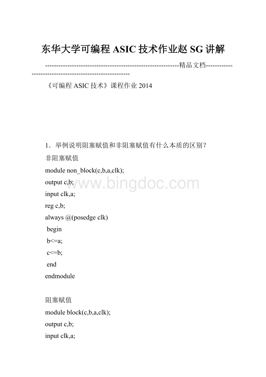
东华大学可编程ASIC技术作业赵SG讲解.docx
《东华大学可编程ASIC技术作业赵SG讲解.docx》由会员分享,可在线阅读,更多相关《东华大学可编程ASIC技术作业赵SG讲解.docx(17页珍藏版)》请在冰点文库上搜索。

东华大学可编程ASIC技术作业赵SG讲解
------------------------------------------------------------精品文档--------------------------------------------------------
《可编程ASIC技术》课程作业2014
1.举例说明阻塞赋值和非阻塞赋值有什么本质的区别?
非阻塞赋值
modulenon_block(c,b,a,clk);
outputc,b;
inputclk,a;
regc,b;
always@(posedgeclk)
begin
b<=a;
c<=b;
end
endmodule
阻塞赋值
moduleblock(c,b,a,clk);
outputc,b;
inputclk,a;
regc,b;
always@(posedgeclk)
begin
b=a;
c=b;
end
endmodule
非阻塞赋值仿真波形图
阻塞赋值仿真波形图
由此可见阻塞赋值是并行赋值,非阻塞赋值是随机的。
1数据选择器。
42.用持续赋值语句描述一个选的数据选择器程序:
4选1modulemux4_1(out,in1,in2,in3,in4,sel1,sel2);
inputin1,in2,in3,in4;
outputout;
inputsel1,sel2;
assignout=sel1?
(sel2?
in4:
in3):
(sel2?
in2:
in1);
endmodule
3.设计一个功能和引脚与74138类似的译码器,并仿真。
译码器程序:
moduleencoder(out,in,en);
output[7:
0]out;/*定义八位二进制码输出口*/
input[2:
0]in;/*定义三位二进制码输入口*/
input[2:
0]en;/*三个使能端*/
reg[7:
0]out;
always@(inoren)
begin
if(en==3'b100)
case(in)
3'd0:
out=8'b11111110;
3'd1:
out=8'b11111101;
3'd2:
out=8'b11111011;
3'd3:
out=8'b11110111;
3'd4:
out=8'b11101111;
3'd5:
out=8'b11011111;
3'd6:
out=8'b10111111;
3'd7:
out=8'b01111111;
endcase
elseout=8'b11111111;
end
endmodule
4.设计一个4位、可预置、可清零的移位寄存器,并仿真。
可预置、可清零的移位寄存器程序:
moduleshift_register(out,in,reset,set,clk);
output[7:
0]out;//定义四位输出端
inputin,reset,set,clk;//输入信号、清零端、置数端、时钟信号
reg[7:
0]out;
reg[7:
0]md;//置数寄存器
always@(posedgeclk)
begin
beginmd=8'b00001101;end//这里预置数为00001101,可以根据需要更改
if(reset)
beginout<=0;end
else
begin
if(set)
beginout<=md;end//置数信号为1,置数
else
beginout<={out,in};end
end
end
endmodule
5.设计一个上升沿触发的可预置、可清零16进制计数器,并仿真。
如果要改为10进制计数器,应对该设计做哪些修改?
modulecounter_16(Q,en,clock,clear,S);
output[3:
0]Q;
input[3:
0]S;
inputen,clock,clear;
reg[3:
0]Q;
always@(posedgeclock)
begin
if(clear==0)
begin
Q<=4'b0000;
end
elseif(en==1)
begin
Q<=S;
end
else
begin
Q<=Q+1'b1;
end
end
endmodule
10进制计数器
修改增加if(Q>=4'b1001)Q<=4'b0000;//当Q的值大于等于9,跳到0
6.分别用结构描述、数据流描述、行为描述三种方式,设计一个2位加法器,并比较上述三种方式各自的优缺点。
结构描述
modulefull_add(a,b,cin,sum,cout);
inputa,b,cin;
outputsum,cout;
wires1,m1,m2,m3;
and(m1,a,b),(m2,b,cin),(m3,a,cin);
xor(s1,a,b),(sum,s1,cin);or(cout,m1,m2,m3);
endmodule
‘include“full_add.v”
moduleadd_2_1(sum,cout,a,b,cin);
inputcin;
input[1:
0]a,b;
output[1:
0]sum;
outputcout;
full_addf0(a[0],b[0],cin,sum[0],cin1);//级联
full_addf1(a[0],b[0],cin1,sum[1],cout);
endmodule
数据流描述
moduleadd_2_2(a,b,cin,sum,cout);
inputcin;
input[1:
0]a,b;
output[1:
0]sum;
outputcout;
assign{cout,sum}=a+b+cin;
endmodule
行为描述
moduleadd_2_3(cout,sum,a,b,cin);
output[1:
0]sum;
outputcout;
input[1:
0]a,b;
inputcin;
reg[1:
0]sum;
regcout;
always@(aorborcin)
begin
{cout,sum}=a+b+cin;
end
endmodule
7.利用状态机设计一个序列检测器,该检测器在有“101”序列输入时输出为1,其他输入情况下,输出为0。
请画出状态转移图,并用Verilog语言描述实现,并仿真。
.
状态说明:
S0:
表示初始状态;
S1:
表示检测到一个“1”信号;
S2:
表示检测到一个“10”信号;
S3:
表示检测到一个“101”信号;
序列检测器程序:
moduleserial_detected(out,in,clk,reset);
outputout;/*结果输出端*/
inputin;/*串行输入的数据*/
inputreset,clk;/*清零信号、时钟信号*/
regout;
reg[2:
0]S,NS;
parameterS0=2'b00,S1=2'b01,S2=2'b10,S3=2'b11;/*状态编码*/
always@(posedgeclkornegedgereset)/*根据输入信号更新状态*/
begin
if(!
reset)S<=S0;
elseS<=NS;
end
always@(Sorin)/*根据输入,锁存记忆输入信号*/
begin
case(S)
S0:
if(in)NS=S1;
elseNS=S0;
S1:
if(in)NS=S1;
elseNS=S2;
S2:
if(in)NS=S3;
elseNS=S0;
S3:
if(in)NS=S1;
elseNS=S2;
endcase
end
always@(Sorresetorin)/*输出对应的结果*/
begin
if(!
reset)out<=0;
elseif(S==S3)out<=1;
elseout<=0;
end
endmodule
8.设计一个加法器,实现sum=a0+a1+a2+a3,a0、a1、a2、a3宽度都是8位。
如用下面两种方法实现,哪种方法更好一些(即速度更快and/or资源更省)。
(1)sum=((a0+a1)+a2)+a3
(2)sum=(a0+a1)+(a2+a3)
9.用流水线技术对上例中的sum=((a0+a1)+a2)+a3的实现方式进行优化,对比最高工作频率,并分析说明:
流水线设计技术为什么能提高数字系统的工作频率?
未采用流水线技术程序:
moduleadder8_1(sum,cout,cout1,cout2,a1,a2,a3,a4,cin,clk);
output[7:
0]sum;/*和*/
outputcout1,cout2,cout;/*每执行一个加法产生的进位信号*/
input[7:
0]a1,a2,a3,a4;/*四个八位二进制数*/
inputcin,clk;/*cin为低位进位信号,低位加法时为0,clk为时钟信号*/
reg[7:
0]S1,S2,sum;
regcout1,cout2,cout;
always@(posedgeclk)
begin
{cout1,S1}=a1+a2+cin;/*第一个时钟来执行第一步加法*/
end
always@(posedgeclk)
begin
{cout2,S2}=S1+a3;/*第二个时钟来执行第二步加法*/
end
always@(posedgeclk)
begin
{cout,sum}=S2+a4;/*第三个时钟来执行第三步加法*/
end
endmodule
采用流水线技术程序:
moduleaddder8_3(cout1,cout2,cout3,sum,a1,a2,a3,a4,cin,clk);
output[7:
0]sum;/*总和*/
outputcout1,cout2,cout3;/*每执行两个数相加产生的进位信号*/
input[7:
0]a1,a2,a3,a4;/*四个加数*/
inputcin,clk;/*低位进位信号,作低位加法器为0、时钟信号*/
reg[7:
0]sum,sum1,sum2;
regcout1,cout2,cout3,firstc,secondc,thirdc;
reg[3:
0]
tempa1,tempa2,tempa3,tempb1,tempb2,tempb3,firstsum,secondsum,thirdsum;/*存储每四位相加的寄存器类型数*/
always@(posedgeclk)
begin
{firstc,firstsum}=a1[3:
0]+a2[3:
0]+cin;/*a1和a2低四位相加*/
tempa1=a1[7:
4];
tempb1=a2[7:
4];
end
always@(posedgeclk)
begin
{cout1,sum1[7:
4]}=tempa1+tempb1+firstc;/*a2和a2高四位相加*/
sum1[3:
0]=firstsum;
end
always@(posedgeclk)
begin
{secondc,secondsum}=sum1[3:
0]+a3[3:
0];/*前两数的和的低四位和a3低四位相加*/
tempa2=sum1[7:
4];
tempb2=a3[7:
4];
end
always@(posedgeclk)
begin
a3前两数的和的高四位和{cout2,sum2[7:
4]}=tempa2+tempb2+secondc;/**/
高四位相加sum2[3:
0]=secondsum;
end
always@(posedgeclk)
begin
低四a4{thirdc,thirdsum}=sum2[3:
0]+a4[3:
0];/*前三数的和的低四位和*/
位相加tempa3=sum2[7:
4];
tempb3=a4[7:
4];
end
always@(posedgeclk)
begin
高前两数的和的高四位和a2{cout3,sum[7:
4]}=tempa3+tempb3+thirdc;/**/
四位相加sum[3:
0]=thirdsum;
end
endmodule
一级的寄存器组将大的组合逻辑切割成小的组合逻辑,以牺牲电路的面积来换取速度的。
10.分析下列的VerilogHDL模块,画出对应的逻辑图或写出逻辑表达式(组),并概括地说明其逻辑功能。
moduleexe1(out,d3,d2,d1,d0,s1,s0);
outputout3,out2,out1,out0;
inputd3,d2,d1,d0,s1,s0;
not(not_s1,s1),(not_s0,s0);
and(out0,d0,not_s1,not_s0),(out1,d1,not_s1,s0);
and(out2,d2,s1,not_s0),(out3,d3,s1,s0);
or(out,out0,out1,out2,out3);
endmodule
根据不同的s1和s0,输出通道进行变化:
(1)当s1=0,s0=0时,out0=d0;
(2)当s1=0,s0=1时,out1=d1;
(3)当s1=1,s0=0时,out2=d2;
(4)当s1=1,s0=1时,out3=d3。
逻辑表达式组:
out0=S1S0d0
out1=S1S0d1
out2=S1S0d2
out3=S1S0d3
out=out0+out1+out2+out3
实现的逻辑功能就是典型的数据通道选择器
模块,用时序波图形或流程框图描述其行为,并.分析下列的VerilogHDL11概括地说明其逻辑功能。
moduleexe2(fd_out,clk,d,clr);
outputfd_out;
regfd_out;
input[15:
0]d;
inputclk,clr;
reg[15:
0]cnt;
always@(posedgeclk)
begin
if(!
clr)cnt<=4'h0000;
elsebegin
cnt<=cnt-1;
if(cnt==0)beginfd_out<=1;cnt<=d;end
elsefd_out<=0;
end
end
endmodule
该程序实现的是可变模的减法计数器,输出的是每当到达设定模值就输出1,相当于对设定模进行检测。
12.分析下列的VerilogHDL模块,写出对应的逻辑表达式(组)或真值表,并概括地说明其逻辑功能。
moduleexe3(op_result,func_sel,op_a,op_b);
output[7:
0]op_result;
input[2:
0]func_sel;
input[3:
0]op_a,op_b;
reg[7:
0]op_result;
always@(func_selorop_aorop_b)
begin
case(func_sel)
op_result<=op_a+op_b;
3'b000:
3'b001:
op_result<=op_a-op_b;
op_result<=op_a*op_b;3'b010:
op_result<=op_a/op_b;3'b011:
op_result<=op_a&op_b;3'b100:
op_result<=op_a|op_b;3'b101:
op_result<=op_a^op_b;3'b110:
op_result<=op_a~^op_b;
3'b111:
endcase
end
endmodule
(1)当fun_sel=000时,op_result=op_a+op_b
(2)当fun_sel=001时,op_result=op_a-op_b;
(3)当fun_sel=010时,op_result=op_a*op_b;
(4)当fun_sel=011时,op_result=op_a/op_b;
(5)当fun_sel=100时,op_result=op_a&op_b;
(6)当fun_sel=101时,op_result=op_a|op_b;
(7)当fun_sel=110时op_result=op_a^op_b;
(8)当fun_sel=111时op_result=op_a~^op_b;
由此可知,该段程序实现的功能是:
根据不同的输入选择信号(000,001,010,011,100,101,110,111),对于两个四位二进制数进行加、减、乘、除、与、或、异或、同或运算。