实验5 SecPath防火墙虚拟防火墙实验指导.docx
《实验5 SecPath防火墙虚拟防火墙实验指导.docx》由会员分享,可在线阅读,更多相关《实验5 SecPath防火墙虚拟防火墙实验指导.docx(26页珍藏版)》请在冰点文库上搜索。
实验5SecPath防火墙虚拟防火墙实验指导
实验5SecPath防火墙虚拟防火墙实验指导
5.1实验内容与目标
完成本实验,您应该能够:
●了解虚拟防火墙的基本原理
●掌握虚拟防火墙的基本配置
5.2实验组网图
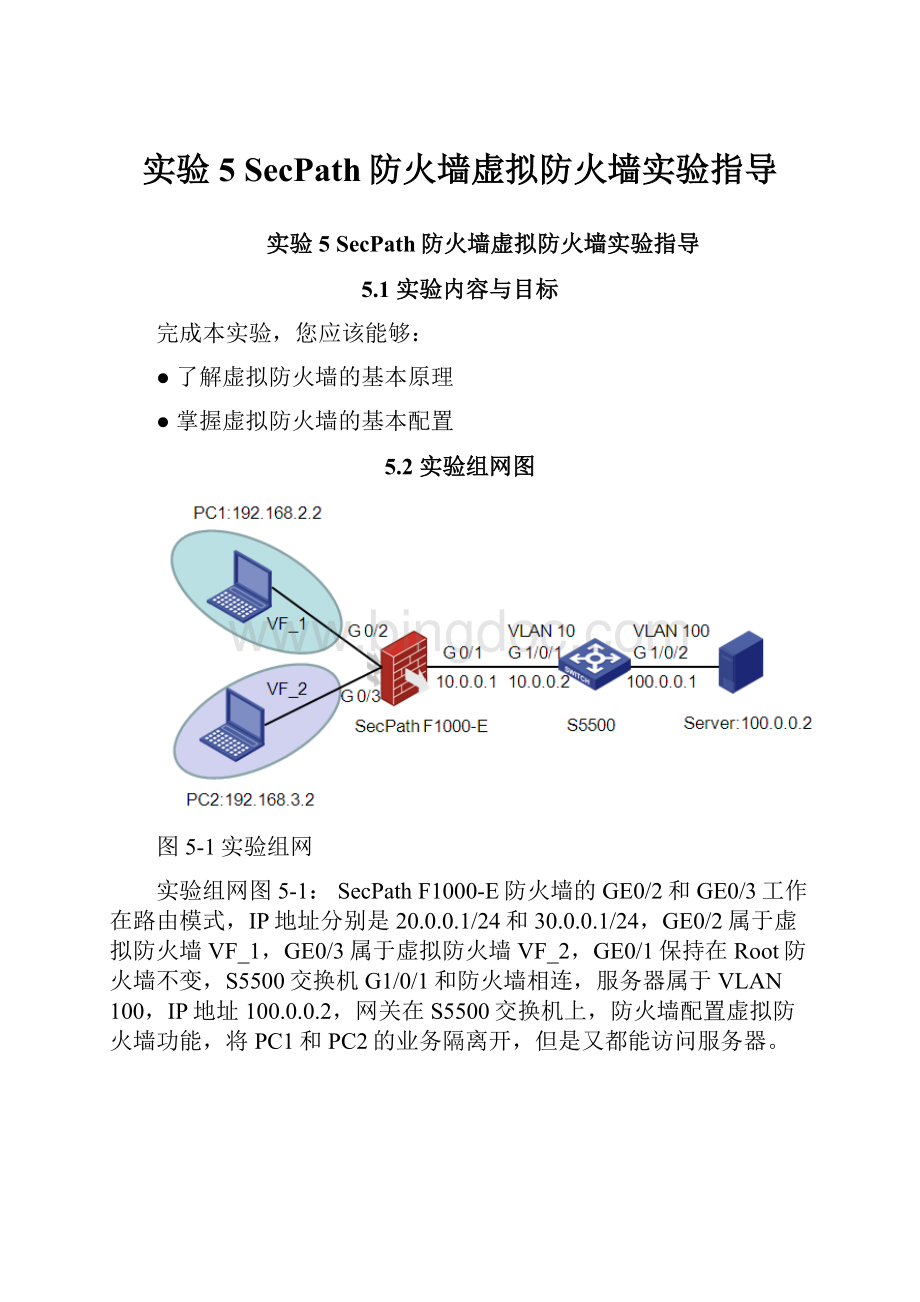
图5-1实验组网
实验组网图5-1:
SecPathF1000-E防火墙的GE0/2和GE0/3工作在路由模式,IP地址分别是20.0.0.1/24和30.0.0.1/24,GE0/2属于虚拟防火墙VF_1,GE0/3属于虚拟防火墙VF_2,GE0/1保持在Root防火墙不变,S5500交换机G1/0/1和防火墙相连,服务器属于VLAN100,IP地址100.0.0.2,网关在S5500交换机上,防火墙配置虚拟防火墙功能,将PC1和PC2的业务隔离开,但是又都能访问服务器。
图5-2实验组网
实验组网图5-2:
SecPathF1000-E防火墙的GE0/2和GE0/3工作在路由模式,IP地址分别是20.0.0.1/24和30.0.0.1/24,GE0/1工作在二层模式,通过VLAN虚接口和交换机互联,GE0/2和Vlan-interface20属于虚拟防火墙VF_1,GE0/3和Vlan-interface30属于虚拟防火墙VF_2,服务器属于VLAN100,IP地址100.0.0.2,网关在S5500交换机上,防火墙配置虚拟防火墙功能,VF_1运行OSPF路由协议和交换机互通,VF_2配置静态路由,将PC1和PC2的业务以及路由隔离开,同时又能访问服务器。
5.3背景需求
虚拟设备就是将一个物理防火墙划分为多个逻辑防火墙来使用,防火墙部署在用户或者服务器前端,通过虚拟防火墙功能把不同用户或者不同业务隔离开来。
5.4实验设备和器材
本实验所需之主要设备器材如表5-1所示。
表5-1实验设备和器材
名称和型号
版本
数量
描述
SecPathF1000-E
CMWF3169P07
1
S5500
CMWR2208
1
PC
WindowsXPSP2
2
服务器
WindowsServer
1
可以用普通PC模拟
第5类UTP以太网连接线
--
2
5.5实验过程
实验任务一:
基本网络配置
步骤一:
交换机基本配置
交换机命令行配置如下:
#
vlan10
#
vlan100
#
interfaceVlan-interface10
ipaddress10.0.0.2255.255.255.0
#
interfaceVlan-interface100
ipaddress100.0.0.1255.255.255.0
#
interfaceGigabitEthernet1/0/1
portaccessvlan10
#
interfaceGigabitEthernet1/0/2
portaccessvlan100
#
iproute-static0.0.0.00.0.0.010.0.0.1
#
步骤二:
防火墙接口地址和路由配置
防火墙命令行配置如下:
#
interfaceGigabitEthernet0/1
portlink-moderoute
ipaddress10.0.0.1255.255.255.0
#
interfaceGigabitEthernet0/2
portlink-moderoute
ipaddress192.168.2.1255.255.255.0
#
interfaceGigabitEthernet0/3
portlink-moderoute
ipaddress192.168.3.1255.255.255.0
#
iproute-static0.0.0.00.0.0.010.0.0.2
#
实验任务二:
虚拟防火墙基本配置
步骤一:
创建虚拟设备
进入防火墙WEB管理界面后,单击“设备管理>虚拟设备管理>虚拟设备配置”。
单击“新建”按钮创建两个虚拟设备。
步骤二:
给虚拟防火墙分配接口和VLAN
进入Root防火墙WEB管理界面,单击“设备管理>虚拟设备管理>接口成员”页面,把GE0/2分配给VF_1防火墙,GE0/3分配给VF_2防火墙,其它接口保持不变,仍然属于Root防火墙。
进入Root防火墙WEB管理界面,单击“设备管理>虚拟设备管理>VLAN成员”页面,把VLAN20分给虚拟防火墙VF_1,VLAN30分给虚拟防火墙VF_2。
步骤三:
登录虚拟防火墙
进入防火墙WEB管理界面,单击“设备管理>虚拟设备管理>虚拟设备选择”。
选中“VF_1”
实验任务三:
同一虚拟防火墙域间策略配置
步骤一:
创建安全区域
新建的虚拟设备没有缺省的安全区域,全部需要手工配置。
进入防火墙WEB管理界面后,单击“防火墙>安全区域”,单击“新建”按钮,创建安全区域。
再创建Untrust区域:
步骤二:
接口加入安全区域
进入防火墙WEB管理界面,单击“设备管理>安全域”,编辑安全区域,把GE0/2加入VF_1_Trust区域。
同样的方法把GE0/1加入VF_1_Untrust区域。
步骤三:
配置同一虚拟防火墙的域间策略
进入“防火墙>安全策略>域间策略”页面,单击“新建”按钮创建VF_1_Untrust到VF_1_Trust区域的域间策略。
步骤四:
查看实验结果
在PC1上可以ping通Server:
C:
\DocumentsandSettings\z07119>ping100.0.0.2
Pinging100.0.0.2with32bytesofdata:
Replyfrom100.0.0.2:
bytes=32time=12msTTL=126
Replyfrom100.0.0.2:
bytes=32time<1msTTL=126
Replyfrom100.0.0.2:
bytes=32time<1msTTL=126
Replyfrom100.0.0.2:
bytes=32time<1msTTL=126
Pingstatisticsfor100.0.0.2:
Packets:
Sent=4,Received=4,Lost=0(0%loss),
Approximateroundtriptimesinmilli-seconds:
Minimum=0ms,Maximum=12ms,Average=3ms
配置完域间策略后Server也能ping通PC1:
C:
\DocumentsandSettings\zhaiyunbo>ping192.168.2.2
Pinging192.168.2.2with32bytesofdata:
Replyfrom192.168.2.2:
bytes=32time=17msTTL=126
Replyfrom192.168.2.2:
bytes=32time<1msTTL=126
Replyfrom192.168.2.2:
bytes=32time<1msTTL=126
Replyfrom192.168.2.2:
bytes=32time<1msTTL=126
Pingstatisticsfor192.168.2.2:
Packets:
Sent=4,Received=4,Lost=0(0%loss),
Approximateroundtriptimesinmilli-seconds:
Minimum=0ms,Maximum=17ms,Average=4ms
实验任务四:
不同虚拟防火墙的域间策略配置
在VF_1和VF_2配置共享区域,实现PC2到Server直接的互访,缺省情况下,不同虚拟防火墙的区域不能直接互访。
步骤一:
VF_2防火墙基本配置
进入VF_2防火墙的web管理界面,创建VF_Trust区域,并把GE0/3加入VF_2_Trust区域。
步骤二:
配置VF_1共享区域
l不同虚拟防火墙之间的互访是通过共享域实现的,需要把VF_1的GE0/1所在的安全区域配置成共享区域,设置成共享区域以后,其它虚拟防火墙的任一一个区域都可以访问这个共享区域,不需要配置域间策略,所以PC2能直接访问Server了。
进入防火墙WEB界面后,在“防火墙>安全区域”页面,编辑安全区域,共享属性设置成YES。
步骤三:
配置域间策略
如果需要限制VF_2到VF_1共享区域的访问,可以配置域间策略实现。
进入VF_2防火墙web管理页面,在“防火墙>安全策略>域间策略”页面,配置VF_2_Trust到VF_1_Untrust区域的域间策略禁止PC2访问Server。
步骤四:
查看实验结果
1.VF_1的VF_1_Trust区域没有配置共享区域,所以PC2不能ping通PC1:
C:
\DocumentsandSettings\z07119>ping192.168.2.2
Pinging192.168.2.2with32bytesofdata:
Requesttimedout.
Requesttimedout.
Requesttimedout.
Requesttimedout.
Pingstatisticsfor192.168.2.2:
Packets:
Sent=4,Received=0,Lost=4(100%loss),
2.VF_1的VF_1_Untrust被设置成共享区域,所以PC2可以ping通Server:
C:
\DocumentsandSettings\z07119>ping100.0.0.2
Pinging100.0.0.2with32bytesofdata:
Replyfrom100.0.0.2:
bytes=32time=19msTTL=126
Replyfrom100.0.0.2:
bytes=32time<1msTTL=126
Replyfrom100.0.0.2:
bytes=32time<1msTTL=126
Replyfrom100.0.0.2:
bytes=32time<1msTTL=126
Pingstatisticsfor100.0.0.2:
Packets:
Sent=4,Received=4,Lost=0(0%loss),
Approximateroundtriptimesinmilli-seconds:
Minimum=0ms,Maximum=19ms,Average=4ms
3.在VF_2配置域间策略,禁止VF_2_Trust到VF_1_Untrust区域互访后,PC2不能ping通Server:
C:
\DocumentsandSettings\z07119>ping100.0.0.2
Pinging100.0.0.2with32bytesofdata:
Requesttimedout.
Requesttimedout.
Requesttimedout.
Requesttimedout.
Pingstatisticsfor100.0.0.2:
Packets:
Sent=4,Received=0,Lost=4(100%loss),
实验任务五:
虚拟防火墙和VPN多实例配置
前面的实验各个虚拟防火墙在安全层面实现了虚拟化,一台设备被虚拟成两台,但是这两台设备共享一个全局的路由表,通过和VPN多实例的配合可以实现不同虚拟防火墙之间路由的隔离,达到真正意义上的虚拟防火墙。
本实验在防火墙上创建两个虚拟防火墙,VF_1运行OSPF路由,VF_2配置静态路由和对端互联实验组网如图6-2所示
步骤一:
交换机配置
网络拓扑不变,防火墙和交换机通VLAN虚接口实现三层互联,具体配置如下:
#
vlan20
#
vlan30
#
vlan100
#
interfaceVlan-interface20
ipaddress20.0.0.2255.255.255.0
#
interfaceVlan-interface30
ipaddress30.0.0.2255.255.255.0
#
interfaceVlan-interface100
ipaddress100.0.0.1255.255.255.0
#
interfaceGigabitEthernet1/0/1
portlink-modebridge
portlink-typetrunk
porttrunkpermitvlan12030
#
interfaceGigabitEthernet1/0/2
portlink-modebridge
portaccessvlan100
#
ospf1
area0.0.0.0
network20.0.0.00.0.0.255
network100.0.0.00.0.0.255
#
iproute-static192.168.3.0255.255.255.030.0.0.1
#
步骤二:
防火墙命令行配置
#
ipvpn-instanceVF_1
route-distinguisher100:
1
#
ipvpn-instanceVF_2
route-distinguisher200:
1
#
vlan20
#
vlan30
#
interfaceVlan-interface20
ipbindingvpn-instanceVF_1
ipaddress20.0.0.1255.255.255.0
#
interfaceVlan-interface30
ipbindingvpn-instanceVF_2
ipaddress30.0.0.1255.255.255.0
#
interfaceGigabitEthernet0/2
portlink-moderoute
ipbindingvpn-instanceVF_1
ipaddress192.168.2.1255.255.255.0
#
interfaceGigabitEthernet0/3
portlink-moderoute
ipbindingvpn-instanceVF_2
ipaddress192.168.3.1255.255.255.0
#
interfaceGigabitEthernet0/1
portlink-modebridge
portlink-typetrunk
porttrunkpermitvlan12030
#
ospf1vpn-instanceVF_1
area0.0.0.0
network192.168.2.00.0.0.255
network20.0.0.00.0.0.255
#
iproute-staticvpn-instanceVF_2100.0.0.0255.255.255.030.0.0.2
#
步骤三:
防火墙WEB页面配置
进入防火墙WEB管理界面后,单击“设备管理>虚拟设备管理>虚拟设备配置”。
单击“新建”按钮创建两个虚拟设备。
进入Root防火墙WEB管理界面,单击“设备管理>虚拟设备管理>接口成员”页面,把GE0/2、VLAN20以及Vlan-interface20分配给VF_1防火墙,GE0/3、VLAN30以及Vlan-interface30分配给VF_2防火墙,其它接口保持不变,仍然属于Root防火墙。
进入防火墙WEB管理界面,单击“设备管理>虚拟设备管理>虚拟设备选择”。
选中“VF_1”
单击“防火墙>安全区域”,单击“新建”按钮,创建安全区域。
再创建Untrust区域:
把GE0/2加入VF_1_Trust区域,Vlan-interface20和GE0/1的VLAN20加入VF_1_Untrust区域。
进入VF_1虚拟防火墙web页面,单击“防火墙>安全策略>域间策略”,单击“新建”按钮创建VF_1_Untrust到VF_1_Trust区域的域间策略。
同样的方式,进入VF_2虚拟防火墙,创建VF_2_Trust区域和VF_2_Untrust区域,然后把GE0/3加入VF_2_Trust区域,Vlan-interface30和GE0/1的VLAN30加入VF_2_Untrust区域。
然后再创建VF_2_Utrust到VF_2_Trust的域间策略。
步骤四:
查看实验结果
1.配置完成VF_1以及OSPF以后,VF_1能学到100.0.0.0/24的路由,S5500能学到192.168.2.0/24的路由,PC1可以ping通Server,但是Serverping不通PC1。
[FW-1]disiprouting-tablevpn-instanceVF_1
RoutingTables:
VF_1
Destinations:
7Routes:
7
Destination/MaskProtoPreCostNextHopInterface
20.0.0.0/24Direct0020.0.0.1Vlan20
20.0.0.1/32Direct00127.0.0.1InLoop0
100.0.0.0/24OSPF10220.0.0.2Vlan20
127.0.0.0/8Direct00127.0.0.1InLoop0
127.0.0.1/32Direct00127.0.0.1InLoop0
192.168.2.0/24Direct00192.168.2.1GE0/2
192.168.2.1/32Direct00127.0.0.1InLoop0
[S5500]displayiprouting-table
RoutingTables:
Public
Destinations:
10Routes:
10
Destination/MaskProtoPreCostNextHopInterface
20.0.0.0/24Direct0020.0.0.2Vlan20
20.0.0.2/32Direct00127.0.0.1InLoop0
30.0.0.0/24Direct0030.0.0.2Vlan30
30.0.0.2/32Direct00127.0.0.1InLoop0
100.0.0.0/24Direct00100.0.0.1Vlan100
100.0.0.1/32Direct00127.0.0.1InLoop0
127.0.0.0/8Direct00127.0.0.1InLoop0
127.0.0.1/32Direct00127.0.0.1InLoop0
192.168.2.0/24OSPF10220.0.0.1Vlan20
192.168.3.0/24Static60030.0.0.1Vlan30
C:
\DocumentsandSettings\z07119>ping100.0.0.2
Pinging100.0.0.2with32bytesofdata:
Replyfrom100.0.0.2:
bytes=32time=21msTTL=126
Replyfrom100.0.0.2:
bytes=32time=1msTTL=126
Replyfrom100.0.0.2:
bytes=32time<1msTTL=126
Replyfrom100.0.0.2:
bytes=32time=43msTTL=126
Pingstatisticsfor100.0.0.2:
Packets:
Sent=4,Received=4,Lost=0(0%loss),
Approximateroundtriptimesinmilli-seconds:
Minimum=0ms,Maximum=43ms,Average=16ms
C:
\DocumentsandSettings\zhaiyunbo>ping192.168.2.2
Pinging192.168.2.2with32bytesofdata:
Requesttimedout.
Requesttimedout.
Requesttimedout.
Requesttimedout.
Pingstatisticsfor192.168.2.2:
Packets:
Sent=4,Received=0,Lost=4(100%loss),
2.配置VF_1_Untrust到VF_1_Trust的域间策略以后,Server能ping通PC1。
C:
\DocumentsandSettings\zhaiyunbo>ping192.168.2.2
Pinging192.168.2.2with32bytesofdata:
Replyfrom192.168.2.2:
bytes=32time=30msTTL=126
Replyfrom192.168.2.2:
bytes=32time=1msTTL=126
Replyfrom192.168.2.2:
bytes=32time<1msTTL=126
Replyfrom192.168.2.2:
bytes=32time<1msTTL=126
Pingstatisticsfor192.168.2.2:
Packets:
Sent=4,Received=4,Lost=0(0%loss),
Approximateroundtriptimesinmilli-seconds:
Minimum=0ms,Maximum=30ms,Average=7ms
3.配置完VF_2以及静态路由的配置后,PC2能ping通Server,但是Server不能ping通PC2
[FW-1]displayiprouting-tablevpn-instanceVF_2
RoutingTables:
VF_2
Destinations:
7Routes:
7
Destination/MaskProtoP
 升级会员
升级会员 