Femap网格划分 及交互式网格修改.docx
《Femap网格划分 及交互式网格修改.docx》由会员分享,可在线阅读,更多相关《Femap网格划分 及交互式网格修改.docx(12页珍藏版)》请在冰点文库上搜索。
Femap网格划分及交互式网格修改
Femap网格划分及交互式网格修改
TableofContents
OverviewandSetup1
AccessingtheModel2
SettingtheMeshSizes2
MeshingtheModel4
InteractivelyRefiningtheMesh6
OverviewandSetup
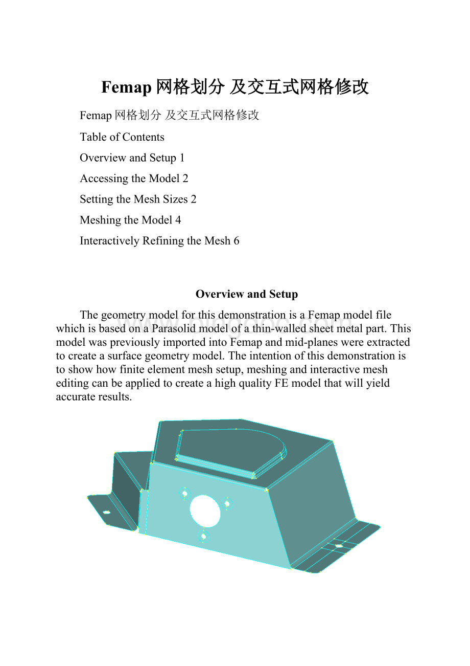
ThegeometrymodelforthisdemonstrationisaFemapmodelfilewhichisbasedonaParasolidmodelofathin-walledsheetmetalpart.ThismodelwaspreviouslyimportedintoFemapandmid-planeswereextractedtocreateasurfacegeometrymodel.Theintentionofthisdemonstrationistoshowhowfiniteelementmeshsetup,meshingandinteractivemesheditingcanbeappliedtocreateahighqualityFEmodelthatwillyieldaccurateresults.
AsmuchuseaspossiblehasbeenmadeoftheModelInfotree,toolbarsandiconsintheuserinterfacetoaccessFemap’sfunctionality.Usuallythereismorethanoneapproachthatcanbeemployedforanygivencommand.
NotethattheParasolidmodelfilewascreatedusingmillimetersastheunitoflength.Allreferencestolengthinthisdemonstrationthereforeareinmillimeters.
Toensurethatyouhaveallofthenecessaryiconsdisplayed,astandardlayoutshouldbeloadedusingtheLoadlayoutcommand:
-SelectFilePreferences
-IntheToolbarssectionoftheUserInterfacetab,selecttheLoadLayoutbutton
-IntheLoadLayoutFromdialog,browsetotheworkshopdirectoryandselecttheWorkshop.layoutfile,andclickOpenandOK
AccessingtheModel
OpentheFemapmodelfilefromtheworkshopdirectory
-SelectFileOpenorselecttheFileOpenicon
ontheModeltoolbar,andbrowsefortheFemapmodelfileFemap_BracketMesh_Start.modfem(此文件可从QQ群199022551下载)–thismodelfilealreadyhassomegeometrymodificationsinreadinessformeshing
SettingtheMeshSizes
Inthissectionwe’llactivatemeshmarkersandcount,setadefaultmeshsize,overridethedefaultbysettingameshsizeonsurfaces(thisactivatesthecount),andsetparticularmeshsizesforthethreewasheroffsetcurvesonthemodel.
-MakesurethattheMeshSizemarkersareswitchedonbyselectingthedropmenurightarrowoftheViewStyleicon
intheViewtoolbar–verifythattheMeshSizeicon
isactivatedinthedropdownmenu
-SelectView/OptionsorclicktheF6shortcutkeyandintheViewOptionsdialogwithintheLabels,EntitiesandColorcategory,selectCurve–MeshSizeintheOptionsarea
-IntheShowAsareaoftheViewOptionsdialog,select3..SymbolsandCountandclickOK
-SelectMesh/MeshControl/DefaultSizeandenteraSizeof5.andclickOK
-SelectMesh/MeshControl/SizeonSurfaceorclickontheMeshSizeonSurfaceicon
intheMeshtoolbar
-IntheEntitySelectdialogclickSelectAllandOK
-IntheAutomaticMeshSizingdialog,enter6.25fortheElementsSizeandclickOKandCancel
-ZoomintotheareathatcontainsthethreewasheroffsetcurvesatthefrontofthemodelbyselectingtheZoomicon
intheViewtoolbar
-SelectMesh/MeshControl/SizeAlongCurveorclickontheMeshSizeonCurveicon
ontheMeshtoolbar,intheEntitySelectiondialogselectallofthewasheroffsetsemi-circularcurvesandthecurvesaroundeachofthethreeholes,verifyselectionbyclickingontheSelectionHighlighticon
andclickOK
-Enter6fortheNumberofElementsintheMeshSizeAlongCurvesdialogandclickOK
-BackintheEntitySelectiondialog,selectallofthesplitcurvesforeachofthethreeholes,andclickOK
-Enter2fortheNumberofElementsintheMeshSizeAlongCurvesdialog,andclickOKandCancel
-SelectthePreviousZoomicon
ontheViewtoolbar
MeshingtheModel
Withthepreparatoryworkfinished,thenexttaskistomeshthemodel.
-SelectMesh/Geometry/SurfaceorclickontheMeshSurfaceicon
ontheMeshtoolbar
-IntheEntitySelectiondialog,clickSelectAllandOK
-IntheAutomeshSurfacesdialogclicktheDefinePropertyicon
-IntheDefinePropertydialogclicktheDefineMaterialicon
-IntheDefineMaterialdialogclicktheLoadbuttonandtheChooseLibrarybutton
-Browsetoinstall_directory/femap11/mat_eng_mm-N-tonne-degC-Watts.esp,selectandclickOpen
-Select16-25-6StainlessSteelandclickOK
-ClickOKtoacceptthematerialdefinition
-IntheDefinePropertydialogenter1.981forthethicknessandclickOK
-IntheAutomeshSurfacesdialogclickOKandthefiniteelementmeshwillbecreated
InteractivelyRefiningtheMesh
Nowthatthemodelhasbeenmeshedwe’llusetheMeshingToolboxwithliveelementqualitycheckingtoverifythatthemeshsettingsdefinedpreviouslyhavecreatedasdesiredandwe’llmakesomefurthermeshadjustmentsinteractively.Inparticularwe’llsuppressahole,mergesomesplitcurvesandtidyupthemeshusingtheMeshSizingandMeshLocatecapabilitieswithintheMeshingToolbox.
-ActivatetheMeshingToolboxbyclickingtheMeshingToolboxicon
inthePanestoolbar
-SelecttheMeshQualitytool
-ClickontheQualityicon
intheheaderlineoficonsintheMeshingToolboxpane
-ClickonthedownarrownexttoQualityTypeJacobianintheMeshQualitytooltoshowthatotherqualitychecksareavailable
-ExpandthetoolnexttoJacobianbyclickingthe+signandsettheMaxAllowableValueto0.8(amorereasonablevalueforaJacobiancheck)
-SelecttheZoomicon
intheViewtoolbarandzoomintotheareaofthemodelwiththethreeholeswithwasheroffsetcurvesforwhichpresetcurvemeshsizeswereset
-SelectthePreviousZoomicon
ontheViewtoolbarthenselecttheZoomicon
againandzoomintotheareaofthemodeltotherightthatcontainedtheflangewiththepad
-SelectthePreviousZoomicon
ontheViewtoolbartoreturntothefullmodelview
-SelecttheZoomicon
intheViewtoolbarandzoomintotheareaofthemodeltotheleft
-ClickontheFeatureSuppressiontoolintheMeshingToolboxdialog
-IntheheadericonsoftheMeshingToolboxselectthedownarrownexttotheRemeshToolsicon
andselectAutoRemesh
-SelecttheSelecticon
(nexttoAutoRemesh)
-Tosuppresstheholeintheflangeselectbothofthedefiningcurves,theholeshoulddisappearandthemodelremeshautomatically,howeverthedefiningcurveswillremainastheholehasonlybeensuppressedandnotdeleted
-DeselecttheSelecticonandrotatethemodelaroundtogetabetterviewoftheleftside–themeshoftheinteriorcornersurfacehalfwayuptheleftsideisuneven,andyoucanseethatthedefiningcurvesateitherendcomprisetwocurves(ascreatedbytheCADsystem),sowe’llcombineeachofthemintoonetogetbettercontrolofthemesh
-SelecttheCombined/CompositeCurvestoolandreselecttheSelecticon
-Selectthemidnodeontheleftandrightcurvesofthecornersurface–themeshisstillunevenbecauseofthemismatchedelementcountonthetopandbottomcurves
-SelecttheMeshSizingtoolwhichwillbeusedtoincreasethemeshdensityofthebottomcurve
-SetOperationtoSetToandenter24fortheNumberofElements
-SelecttheSelecticonandselectthebottomcurveofthecornersurfaceanddeselecttheSelecticon
-Thereisoneelementtotherightjustunderthecornerthatiscoloredred,SelecttheZoomicon
tozoomintothiselement
-Tofixthiselementwe’llmanuallydragoneofthecornernodestochangetheelementshape,selecttheMeshLocatetool
-TheSelectMeshtoEditentryiscurrentlysettoAttachedtoSurface,clickonthedownarrowtotherightandselectAttachedtoSolid
-Nowclickontheicon
nexttothedownarrow,andselectthesolid(thereisonlyonethatcomprisesallsurfacesinthismodel)
-IntheSelectSolid/VolumedialogclickOK
-SelecttheSelecticon
-Pickanddragthenodeoftheredcoloredelementthatisinteriortothemodel,movingituntiltheelementcolorchangestogreen
-DeselecttheSelecticon
Thebracketmodelmeshisnowcompleteandallelementspassthesetqualitycriterion.
-FinallytocleanupthedisplayselectthedropmenurightarrowoftheViewStyleicon
intheViewtoolbaranddeselecttheMeshSizeicon
Thisconcludesthebracketmodelinteractivemeshingdemonstration.
 升级会员
升级会员 