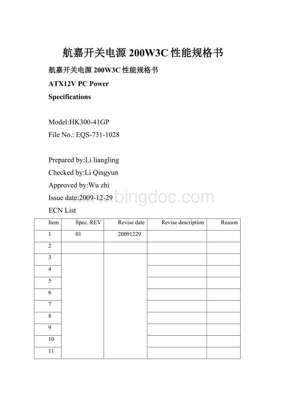
航嘉开关电源200W3C性能规格书.docx
《航嘉开关电源200W3C性能规格书.docx》由会员分享,可在线阅读,更多相关《航嘉开关电源200W3C性能规格书.docx(13页珍藏版)》请在冰点文库上搜索。

航嘉开关电源200W3C性能规格书
航嘉开关电源200W3C性能规格书
ATX12VPCPower
Specifications
Model:
HK300-41GP
FileNo.:
EQS-731-1028
Preparedby:
Liliangling
Checkedby:
LiQingyun
Approvedby:
Wuzhi
Issuedate:
2009-12-29
ECNList
Item
Spec.REV
Revisedate
Revisedescription
Reason
1
01
20091229
2
3
4
5
6
7
8
9
10
11
12
13
HK300-41GPSpecification
1.0InputCharacteristics……………………………………………………………………………………………3
1.1InputVoltageRange
1.2InputFrequencyRange
1.3Inputcurrent
1.4Inrushcurrent
1.5PowerEfficiency
1.6StandbyConsumption
1.7HarmonicCurrent
2.0Outputspecificationdescription……………………………………………………………………………….3
2.1Staticoutputcharacteristics
2.2Cross-loadregulation
2.3DynamicLoad
2.4CapacitiveLoad
2.5Outputconnector
3.0Protection……………………………………………………….……………………………………………….6
3.1OverVoltageProtection
3.2ShortCircuitProtection
3.3OverCurrentProtection
3.4OverPowerProtection
3.5Resetaftershutdown:
4.0TimeSequence………………………………………………….……………………………………………..6
4.1Power-ontime
4.2RiseTime
4.3PWR_OKdelay
4.4PWR_OKRise
4.5AClosstoPWR_OKhold-uptime
4.6PowerFailDelayTime
4.7PowerOK
4.8PS_ON
5.0AuxiliaryOutput………………………………………………….……………………………………………8
6.0Environment…………………………………………………………….……………………………………..8
6.1Operatingambient:
6.2ShippingandStorage:
6.3Altitude:
6.4Cooling
6.5Fanspeedcontrol
7.0SafetyandEMC……………………………………………………….……………………………………….9
7.1SAFETYREQUIREMENTSANDCertify
7.2ConductedandRadiatedEmissions
7.3ESD
7.4EFT
7.5SurgeSusceptibility
7.6Hi-Pot
7.7GroundingContinuityTest
7.8GroundLeakageCurrent:
8.0Mechanical…………………………………………………………………………………………………….10
8.1Mechanicaloutline:
8.2DCwiredrawing
8.3Labeldrawing
9.0ECNList………………………………………………………………………………………………………..11
1.0InputCharacteristics:
1.1InputVoltageRange:
180Vacto265Vac,singlephase.
Table1.InputVoltageRange
RANGE
MINIMUM
NORMAL
MAXIMUM
UNITS
HighRange
180
200~240
265
Vrms
1.2InputFrequencyRange:
50+/-3Hzand60+/-3Hz;NormalFrequencyRange:
50-60Hz
1.3Inputcurrent
Inputcurrentis4AMax.
1.4Inrushcurrent:
Powersupplyinrushcurrentshallbelessthantheratingsofitscriticalcomponents(includingbulkrectifiers,fuses,andsurgelimitingdevice)underallconditionsoflinevoltageofSection1.1.
1.5PowerEfficiency:
70%min.atfullloadandnormalACinput.
1.6HarmonicCurrent:
(1)TheharmonicofthepowerlineandneutralcurrentshallcomplythestandardIEC61000-3-2forclassDequipment.
(2)Measurementshallbeperformedat75Winputpowerandfulloutputload,Inputvoltageshallbe220Vac/50Hzor230Vac/60Hz,Don’ttestinprocessunderlowrange.
2.0OutputCharacteristics:
2.1Staticoutputcharacteristics:
Table2.Staticoutputcharacteristics
OutputVoltage
Load
Regulation
Ripple&Noise
Min
Max
Surge
MaxmVP-P
+5V
0.2A
14A
16A
+/-5%
50mV
+12V
0.6A
12A
16A
+/-5%
120mV
+5VSb
0A
2.0A
+/-5%
50mV
+3.3V
0.1A
12A
+/-5%
50mV
-12V
0A
0.3A
+/-10%
120mV
At25℃
(1)Thetotalcombined3.3V&5Vpowershallnotexceed80W.
(2)Thetotalcombined3.3V/5V/+12Vpowershallnotexceed190W.
(3)Thecontinuousoutputpowershallnotexceed200W.
2.2Thecross-loadregulationindefinedinthematrixbelow(UNIT:
A)
Table3.CrossRegulation
Range
+5V
+12V
-12V
+3.3V
+5Vsb
1
0.20
0.60
0.00
0.10
2.00
2
4.00
12.0
0.30
3.00
2.00
3
6.00
4.00
0.00
4.50
2.00
4
14.0
4.50
0.10
3.00
0.50
5
10.0
8.00
0.30
8.00
0.00
6
4.00
4.00
0.30
12.0
2.00
7
8.00
9.50
0.30
8.00
2.00
Notes:
A0.1uFceramicdiskcapacitorand10uFtantalumcapacitorsshouldbeputacrossoutputterminalsduringripple&noisetest.Theoscilloscopebandwidthissetat20MHzandco-axialprobewillbeusedtomeasureit.
2.3DynamicLoad:
Thefollowingtransientloadsaretobeappliedtotheoutput.Thewaveformshallbeasquarewavewiththeslopeoftheriseandfallat0.1A/s.Thesquarewaveshallhaveafrequency50Hzto10KHzwithadutycycleof10to90%.
TheoutputvoltagesshallnotexceedregulationlimitsasdefinedinTable2underthefollowingcondition:
TRANSIENTVOLTAGETOLERANCE
Table4.DynamicLoadStepSizes
NOM.OUTPUTVOLTAGE(VDC)
CURRENT
Imin
CURRENT
Imax
STEPLOADCHANGE(%)
TRANSIENTTOLERANCE(%)
+5.0
0.3A
14A
30
±5
+12.0V
1.0A
12A
40
±5
+3.3
0.3A
12A
30
5
(Addingexternalcapacitor:
5V/5000uF,12V/5000uF,3.3V/6000uF,-12V/350uF,5Vaux=350uF)
2.4CapacitiveLoad:
ThepowersupplyshouldbeabletopowerupandoperatewiththeregulationlimitsdefinedinTable2,withthefollowingcapacitancessimultaneouslypresentontheDCoutputs.
Table5.OutputCapacitiveLoads
Output
CapacitiveLoad
+12V
5000μF
+5V
5000μF
+3.3V
6000μF
-12V
350μF
+5VSb
350μF
2.5Thepowersupplyshallhavetheoutputconnectorandwireharnessconfigurations.
3.0Protection
3.1OverVoltageProtection:
+5V:
7.0Vmax,+12V:
15.6Vmax,+3.3V:
4.7Vmax.
3.2ShortCircuitProtection:
Themainoutputshallshutdownandlatchoffforshorting+5V,+12V,-12Vor+3.3VrailstoDC-returnandshorting.
3.3OverCurrentProtection
Originalcondition:
ACinput230V~,Outputfullload.:
+3.3V/10A,+12V/8A,-12V/0.3A,5VSB/2A
Increasetheoutputcurrentatthe+5Vrailgraduallyto21A~31A,themainoutputshouldshutdownandlatchoff.
3.4OverPowerProtection:
Themainoutputwillbeshutdownandlatchoffwhenoutputpowerisat240W~320W.
3.5Resetaftershutdown:
Whenthepowersupplylatchesintoshutdownconditionduetoafaultonanoutput(overcurrent,overvoltageorshortcircuit),theprotectionlatchshallresetwithin30SafterthefaulthasbeenremovedandtheON/Offsignalhasswitchedstate.Also,thelatchshallresetwithin30SwhenACpowerhasbeenremoved.
4.0TimeSequence
4.1Power-ontimeT1
Thepower-ontimeisdefinedasthetimefromwhenPS_ON#ispulledlowtowhenthe+12VDC,+5VDC,and+3.3VDCoutputsarewithintheregulationrangesspecifiedinSection2.1.Thepower-ontimeshallbelessthan500ms.
4.2RisetimeT2
Theoutputvoltagesshallrisefrom≤10%ofnominaltowithintheregulationrangesspecifiedinSection2.1within0.1msto20ms.
4.3PWR_OKdelayT3
ThePowerGoodsignalshallhaveaturn-ondelayofatleast100mSbutnotgreaterthan500mSfromthetimethe3.3Vand+5Voutputhasreachedtheirminimumregulationlevel.
4.4PWR_OKrisetimeT4
ThePowerGoodsignalshallhavearisetime(measuredfromthe10%pointtothe90%point)oflessthan10milliseconds.
4.5AClosstoPWR_OKhold-uptimeT5
ThePowerGoodSignalshallremainanuplevelforatleast16msecafterACpowerisremovedandshallgotoadownlevelbeforethe3.3Vor+5Vfallsbelowtheirregulationlimit.
4.6.PowerFailDelayTimeT6
ThePower_Downwarningsignalatleast1.0msecshallhaveapowerGoodSignalchangeLowVoltagetothe3.3Vor+5Vfallsbelowtheirregulationlimit.
4.7PowerOK(POK)
Thepowersupplyshallprovidea“PowerGood”signaltoresetsystemlogic,indicateproperoperationofthepowersupply,andgiveadvancewarningofimpendinglossofregulationatturnoff.
TheelectricalcharacteristicsforthePowerOKoutputdriverareshownbelow:
Table6.PowerOKSignalCharacteristics
PowerOKSignalCharacteristics
SignalType
+5VTTLCompatible
LogicLevelLow
<0.4Vwhilesinking4mA
LogicLevelHigh
Between2.4Vand5Voutputwhilesourcing200μA
High-StateOutputImpedance
1kΩfromoutputtocommon
4.7PS_ON
PS_ONisanactivelow,+5VtolerantTTLsignalthatallowthemotherboardtoremotelycontrolthepowersupply.Aninternalpull-upresistorinsidethepowersupplyshallprovideaTTLhighoutputlogiclevel,onceanACinputvoltagehasbeenappliedtothepowersupply.TheelectricalcharacteristicsforthePS_ONsignalareshownbelow:
Table7.PS-ONSignalCharacteristics
PS-ONSignalCharacteristics
SignalDescription
Min
Max
InputLowVoltage
0.0V
0.8V
InputLowCurrent(Vin=0.4V)
-
-1.6mA
InputHighVoltage(Iin=-200µA)
2.0V
VIHopencircuit
-
5.25V
5.0Auxiliary5VOutput:
The5VauxiliaryoutputwillbeactiveandinregulationwheneveranACinputwithinthespecifiedoperatingrangeisappliedtothepowersupplyinput.ThePS_ONpinofP1willnot
affectthe5Vauxiliaryoutput.
6.0Environment:
6.1Operatingambient:
Table8.Operatingambient
AirTemperature
0to50degreescentigrade
RelativeHumidity
5to95percent,non-condensing
6.2ShippingandStorage:
Table9.ShippingandStorage
AirTemperature
-40to70degreescentigrade
RelativeHumidity
5to95percent,includingcondensation
6.3Altitude:
Operatingto3050meters(10,000ft)
Non-operatingto15250meters(50,000ft).
6.4Cooling:
Thepowersupplyshallprovideforcedaircoolingforthehostsystem.
7.0SafetyandEMC
7.1SAFETYREQUIREMENTSANDCertify
ThepowersupplyhasbeencertifiedbyCCC.TheCCCSafetymarkshallappearontheproduct.
7.2ConductedandRadiatedEmissions:
ConductedandradiatedemissionsofthepowersupplyshallcomplywiththerequirementsofGB9254&EN55022ClassB.
7.3ESD:
ESDofthepowersupplyshallcomplywiththerequirementsofIEC61000-4-2Level3.
7.4EFT:
EFTofthepowersupplyshallcomplywiththerequirementsofIEC61000-4-4Level3.
7.5SurgeSusceptibility:
SurgeSusceptibilityofthepowersupplyshallcomplywiththerequirementsofIEC61000-4-5Level3.
7.6Hi-Pot:
InputtoGND:
Voltage1500VACTime3.0S,Cutoffcurrent10mAMAX
7.7Grounding