DESIGN OF a 5th ORDER BUTTERWORTH LPF.docx
《DESIGN OF a 5th ORDER BUTTERWORTH LPF.docx》由会员分享,可在线阅读,更多相关《DESIGN OF a 5th ORDER BUTTERWORTH LPF.docx(11页珍藏版)》请在冰点文库上搜索。
DESIGNOFa5thORDERBUTTERWORTHLPF
DESIGNOFa5thORDERBUTTERWORTHLOW-PASSFILTERUSINGSALLEN&KEYCIRCUIT
BackgroundTheory:
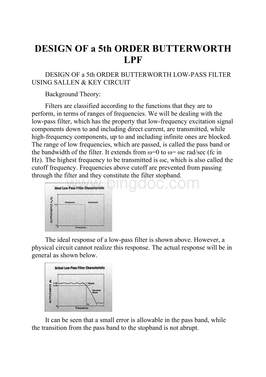
Filtersareclassifiedaccordingtothefunctionsthattheyaretoperform,intermsofrangesoffrequencies.Wewillbedealingwiththelow-passfilter,whichhasthepropertythatlow-frequencyexcitationsignalcomponentsdowntoandincludingdirectcurrent,aretransmitted,whilehigh-frequencycomponents,uptoandincludinginfiniteonesareblocked.Therangeoflowfrequencies,whicharepassed,iscalledthepassbandorthebandwidthofthefilter.Itextendsfromω=0toω=ωcrad/sec(fcinHz).Thehighestfrequencytobetransmittedisωc,whichisalsocalledthecutofffrequency.Frequenciesabovecutoffarepreventedfrompassingthroughthefilterandtheyconstitutethefilterstopband.
Theidealresponseofalow-passfilterisshownabove.However,aphysicalcircuitcannotrealizethisresponse.Theactualresponsewillbeingeneralasshownbelow.
Itcanbeseenthatasmallerrorisallowableinthepassband,whilethetransitionfromthepassbandtothestopbandisnotabrupt.
Thesharpnessofthetransitionfromstopbandtopassbandcanbecontrolledtosomedegreeduringthedesignofalow-passfilter.
Theideallow-passfilterresponsecanbeapproximatedbyarationalfunctionapproximationschemesuchastheButterworthresponse.
TheButterworthResponse
NormalizingH0=1and
Then
findingtherootsofD(s)
Example:
Forn=5
Allthepolesare:
-1.0000
-0.8090+0.5878i
-0.8090-0.5878i
-0.3090+0.9511i
-0.3090-0.9511i
0.3090+0.9511i
0.3090-0.9511i
1.0000
0.8090+0.5878i
0.8090-0.5878
POLELOCATIONS
Thepolesaredistributedoverthecircleofradius1(
).Neverapoleintheimaginaryaxis.
FindingH(s)fromH(s)H(-s):
H(s)isassignedallRHSpolesH(-s)isassignedallLHSpoles
Followingthisprocedure,theButterworthLPFH(s)(H0=1,wc=1rad/sec)canbefoundforvariousfiltersofordern.
WecanuseMATLABtogetthisdenominatorpolynomial(Butterworthpolynomial)
InMATLAB(code):
all_poles=roots([(-1)^n,zeros(1,2*n-1),1])
poles=all_poles(find(real(all_poles)<0))
Den=poly(poles)
CircuitDesign:
WewanttodesignofafifthorderButterworthlow-passfilterwithacutofffrequencyof10KHz.
Duringthedesignwemakeuseofmagnitudeandfrequencyscalingandalsooftheuniformchoiceof
asacharacterizingfrequencywillappearinalldesignsteps,exceptforthelastwherethede-normalized(actual)valueswillbefound.
CircuitImplementation:
ImplementationofthecircuitisdoneusingtheSallen&KeyTopology.
thisisofthegeneralform
Ifk=1,
taking
Torealizea5thorderBLPFoneSallen&Keystagewithasingleop-ampisrequiredforeverycomplex-conjugatepolepair.Sincen=5(odd),anadditionalnegativepoleisrequiredandweuseanRC/voltagefollower.AlsowemadethechoiceofK=1,whichrequiresthattheinvertingop-ampcircuitbereplacedbyavoltagefollowerasshownbelow.
Tofindactualvalues:
Makeallresistors=
Frequencyscaling=
Multiplyingeachcapacitorby
PerformanceMeasures:
Cutofffrequency=10KHz
Frequency(KHz)
Vin(mV)
Vout(mV)
1.502
500
498.5
2.009
500
493.5
5.782
500
493.7
9.001
500
487
9.6
500
387.5
10.04
500
245.7
11.01
500
225.7
12.04
500
187.5
13.02
500
115.6
14.02
500
90.62
15.06
500
75.00
16.01
500
62.50
17.01
500
47.50
Idealresponse:
Actualresponse:
Fromtherecordedvaluesaftermeasurements.
MeasureddBgainvaluesvs.logfrequencyvalues
CircuitDiagram:
FinalCircuit
Parts:
Part
Quantity
LM324N
LowPowerQuadOperationalAmplifier
1
1KΩresistor
5
0.016μFcapacitor
1
0.019μFcapacitor
1
0.013μFcapacitor
1
0.051μFcapacitor
1
0.0049μFcapacitor
1
9Vbattery
2
References:
DeliyannisT.,YichuangSun,andJ.K.Fidler1999,Continuous-timeActiveFilterDesign,CRCPress,NewYork.
VanValkenburgM.E.,AnalogFilterDesign,1982,OxfordUniversityPress,NewYork.
ChenWai-Kai,Passive&ActiveFilterDesign,Chapter2,pp.50-92
HuelsmanL.P.andP.E.Allen,IntroductiontotheTheoryandDesignofActiveFilters
 升级会员
升级会员 