FPGA VERILOG PID控制.docx
《FPGA VERILOG PID控制.docx》由会员分享,可在线阅读,更多相关《FPGA VERILOG PID控制.docx(14页珍藏版)》请在冰点文库上搜索。
FPGAVERILOGPID控制
PID算法及其FPGA实现
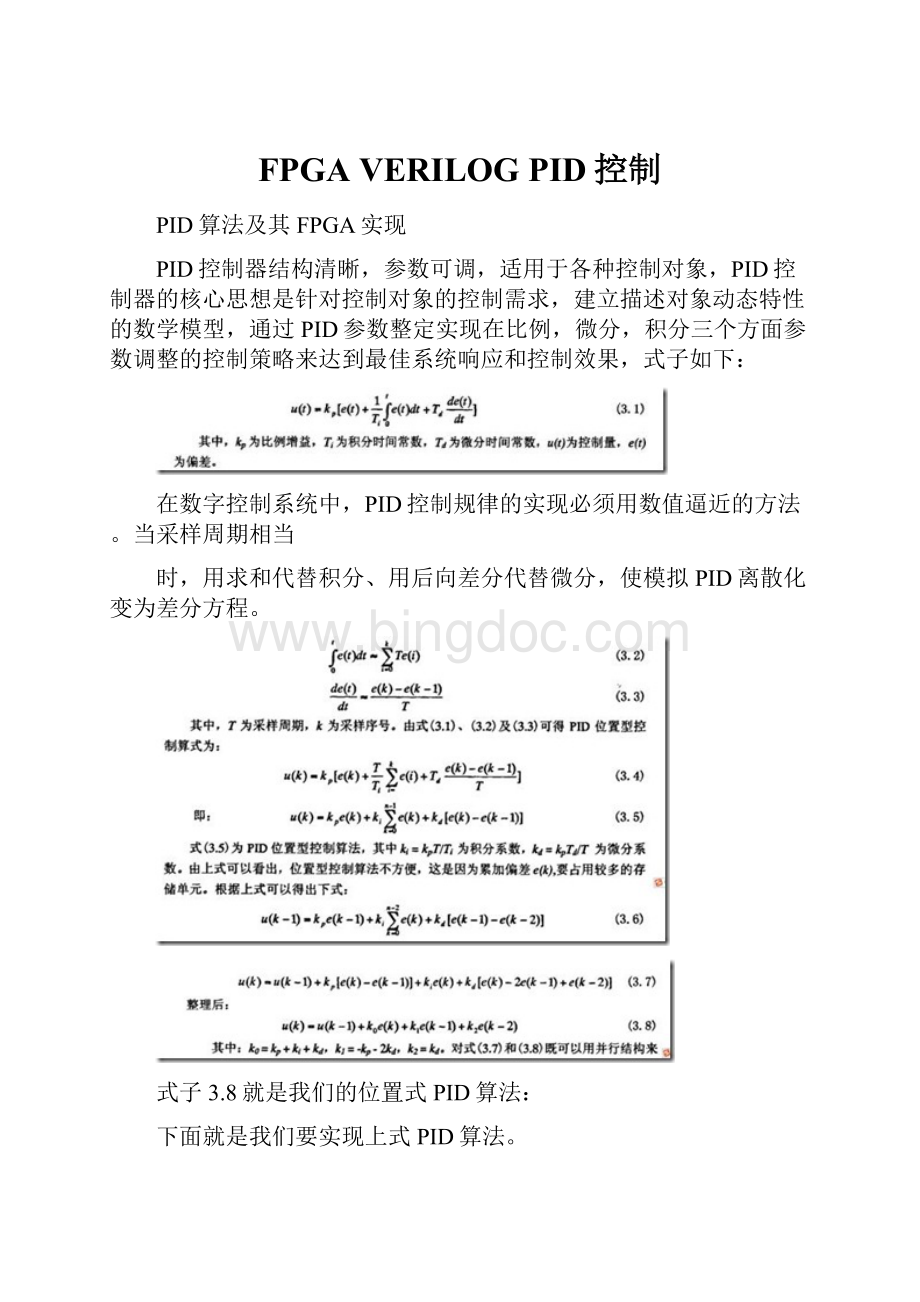
PID控制器结构清晰,参数可调,适用于各种控制对象,PID控制器的核心思想是针对控制对象的控制需求,建立描述对象动态特性的数学模型,通过PID参数整定实现在比例,微分,积分三个方面参数调整的控制策略来达到最佳系统响应和控制效果,式子如下:
在数字控制系统中,PID控制规律的实现必须用数值逼近的方法。
当采样周期相当
时,用求和代替积分、用后向差分代替微分,使模拟PID离散化变为差分方程。
式子3.8就是我们的位置式PID算法:
下面就是我们要实现上式PID算法。
PID的FPGA实现:
得到:
Verilog实现:
viewplaincopytoclipboardprint?
1.`timescale 1ns / 1ps
2.//////////////////////////////////////////////////////////////////////////////////
3.// Company:
4.// Engineer:
5.//
6.// Create Date:
21:
02:
51 05/14/2014
7.// Design Name:
8.// Module Name:
pid
9.// Project Name:
10.// Target Devices:
11.// Tool versions:
12.// Description:
13.//
14.// Dependencies:
15.//
16.// Revision:
17.// Revision 0.01 - File Created
18.// Additional Comments:
19.//
20.//////////////////////////////////////////////////////////////////////////////////
21.module pid(
22. input clk,
23. input rst_n,
24. input [8:
0] error,
25. output reg [16:
0] uk
26. );
27.
28.//reg [16:
0]uk;
29.wire [16:
0]uk_wire;
30.reg [8:
0]error_1,error_2;
31.parameter k0=5;
32.parameter k1=1;
33.parameter k2=1;
34.always @(posedge clk)
35.begin
36. if(!
rst_n)
37. begin
38. error_1<=0;
39. error_2<=0;
40. end
41. else
42. begin
43. error_1<=error;
44. error_2<=error_1;
45. end
46.end
47.
48.//
49.reg [14:
0]uk1;
50.always @(posedge clk)
51.begin
52. if(!
rst_n)
53. begin
54. uk<=0;
55. uk1<=0;
56. end
57. else
58. begin
59. if((uk_wire>17'd15000)&&(uk_wire<17'b1000_0000_0000_00000))
60. begin
61. uk<=17'd15000;
62. end
63. else
64. begin
65. uk1<=uk[14:
0];
66. uk<=uk_wire;
67. end
68. end
69.end
70.
71.wire [14:
0] p0;
72.mult u1 (
73. .b ( k0 ),
74. .a ( error ),
75. .p ( p0 ),
76. .clk(clk)
77. );
78.
79.wire [14:
0] p1;
80.mult u2 (
81. .b ( k1 ),
82. .a ( error_1 ),
83. .p ( p1 ),
84. .clk(clk)
85. );
86.wire [14:
0] p2;
87.mult u3 (
88. .b ( k2 ),
89. .a ( error_2 ),
90. .p ( p2 ),
91. .clk(clk)
92. );
93.
94.wire [15:
0]s1;
95.add u4 (
96. .a ( p0 ),
97. .b ( p1 ),
98. .s ( s1 ),
99. .clk ( clk )
100. );
101.
102.wire [15:
0]s2;
103.add u5 (
104. .a ( p2 ),
105. .b ( uk1 ),
106. .s ( s2 ),
107. .clk ( clk )
108. );
109.
110.add2 u6 (
111. .a ( s1 ),
112. .b ( s2 ),
113. .s ( uk_wire[16:
0] ),
114. .clk (clk)
115. );
116.
117.
118.endmodule
`timescale1ns/1ps////////////////////////////////////////////////////////////////////////////////////Company:
//Engineer:
////CreateDate:
21:
02:
5105/14/2014//DesignName:
//ModuleName:
pid//ProjectName:
//TargetDevices:
//Toolversions:
//Description:
////Dependencies:
////Revision:
//Revision0.01-FileCreated//AdditionalComments:
////////////////////////////////////////////////////////////////////////////////////modulepid(inputclk,inputrst_n,input[8:
0]error,outputreg[16:
0]uk);//reg[16:
0]uk;wire[16:
0]uk_wire;reg[8:
0]error_1,error_2;parameterk0=5;parameterk1=1;parameterk2=1;always@(posedgeclk)beginif(!
rst_n)beginerror_1<=0;error_2<=0;endelsebeginerror_1<=error;error_2<=error_1;endend//reg[14:
0]uk1;always@(posedgeclk)beginif(!
rst_n)beginuk<=0;uk1<=0;endelsebeginif((uk_wire>17'd15000)&&(uk_wire<17'b1000_0000_0000_00000))beginuk<=17'd15000;endelsebeginuk1<=uk[14:
0];uk<=uk_wire;endendendwire[14:
0]p0;multu1(.b(k0),.a(error),.p(p0),.clk(clk));wire[14:
0]p1;multu2(.b(k1),.a(error_1),.p(p1),.clk(clk));wire[14:
0]p2;multu3(.b(k2),.a(error_2),.p(p2),.clk(clk));wire[15:
0]s1;addu4(.a(p0),.b(p1),.s(s1),.clk(clk));wire[15:
0]s2;addu5(.a(p2),.b(uk1),.s(s2),.clk(clk));add2u6(.a(s1),.b(s2),.s(uk_wire[16:
0]),.clk(clk));endmodule
Testbench:
viewplaincopytoclipboardprint?
1.`timescale 1ns / 1ps
2.
3.////////////////////////////////////////////////////////////////////////////////
4.// Company:
5.// Engineer:
6.//
7.// Create Date:
21:
34:
28 05/14/2014
8.// Design Name:
pid
9.// Module Name:
J:
/xilinx_project/pid/test.v
10.// Project Name:
pid
11.// Target Device:
12.// Tool versions:
13.// Description:
14.//
15.// Verilog Test Fixture created by ISE for module:
pid
16.//
17.// Dependencies:
18.//
19.// Revision:
20.// Revision 0.01 - File Created
21.// Additional Comments:
22.//
23.////////////////////////////////////////////////////////////////////////////////
24.
25.module test;
26.
27. // Inputs
28. reg clk;
29. reg rst_n;
30. reg [8:
0] error;
31.
32. // Outputs
33. wire [16:
0] uk;
34.
35. // Instantiate the Unit Under Test (UUT)
36. pid uut (
37. .clk(clk),
38. .rst_n(rst_n),
39. .error(error),
40. .uk(uk)
41. );
42.
43.
44. initial begin
45. // Initialize Inputs
46. clk = 0;
47. rst_n = 0;
48. error = 0;
49.
50. // Wait 100 ns for global reset to finish
51. #40 rst_n=1;
52. #20 error=9'b001111111;
53. #200 error=9'b000111111;
54. #200 error=9'b000011111;
55. #200 error=9'b000001111;
56. #200 error=9'b000000111;
57. #200 error=9'b000000011;
58. #800 error=0;
59. #200 error=9'b111000000;
60. #200 error=9'b111110000;
61. #200 error=9'b111111111;
62. #800 error=0;
63. // #200 error=9'b100000001;
64.
65. // Add stimulus here
66.
67. end
68. always #10 clk=~clk;
69.endmodule
`timescale1ns/1ps//////////////////////////////////////////////////////////////////////////////////Company:
//Engineer:
////CreateDate:
21:
34:
2805/14/2014//DesignName:
pid//ModuleName:
J:
/xilinx_project/pid/test.v//ProjectName:
pid//TargetDevice:
//Toolversions:
//Description:
////VerilogTestFixturecreatedbyISEformodule:
pid////Dependencies:
////Revision:
//Revision0.01-FileCreated//AdditionalComments:
//////////////////////////////////////////////////////////////////////////////////moduletest;//Inputsregclk;regrst_n;reg[8:
0]error;//Outputswire[16:
0]uk;//InstantiatetheUnitUnderTest(UUT)piduut(.clk(clk),.rst_n(rst_n),.error(error),.uk(uk));initialbegin//InitializeInputsclk=0;rst_n=0;error=0;//Wait100nsforglobalresettofinish#40rst_n=1;#20error=9'b001111111;#200error=9'b000111111;#200error=9'b000011111;#200error=9'b000001111;#200error=9'b000000111;#200error=9'b000000011;#800error=0;#200error=9'b111000000;#200error=9'b111110000;#200error=9'b111111111;#800error=0;//#200error=9'b100000001;//Addstimulushereendalways#10clk=~clk;endmodule
中途中mult的实现可以使用LUT或者DSP资源(上一篇博客也有说)
另外在modelsim安装和编译xilinx库时,后面那个是在modelsim建立工程才要指定的,我这里是直接从xilinx中启动modelsimse的,(前提是要将xilinx的编译库添加进modelsim)。
Project-》designproperties
Edit-》Preferences
Process-》ProcessProperties
仿真结果:
不同于altera-modelsim中,那里是要指定vt文件,然后仿真即可,这里没有指定testbench文件:
有几次我鼠标点在uut-pid这里,然后点击simulate,结果可想而知,是不正确的,要点击testbenchtest这个文件,在仿真。
为了在modelsim查看波形,format-》anlogy(custom)
根据幅值设置一个比较合适的参数。
 升级会员
升级会员 